Hydraulic Symbols and Schematic For Beginners How to Read Hydraulic Drawing. Part 02

What’s the Difference Between Hydraulic Circuit Symbols? Machine Design
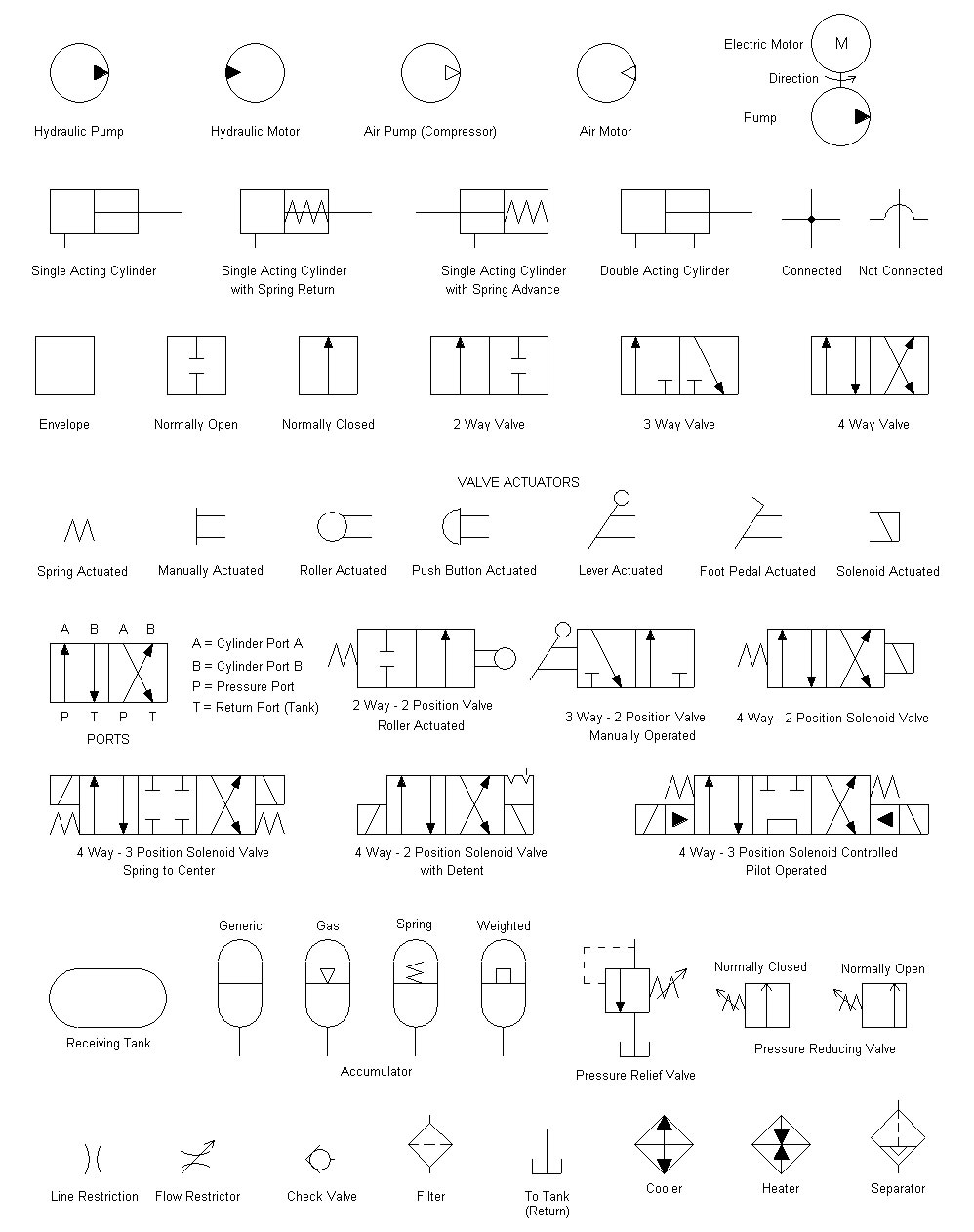
general engineering hydraulic & PNEuMaTic SyMBOlS hydraulic & PneuMaTic SyMBOlS iso 1219-1 covers graphic symbols for both hydraulic and pneumatic equipment. For circuit diagram layout rules see bs iso 1219-2. For port identification and operator marking see iso 9461 (hydraulic) or bs iso 5599 (Pneumatic). graphic symbols for fluid power systems
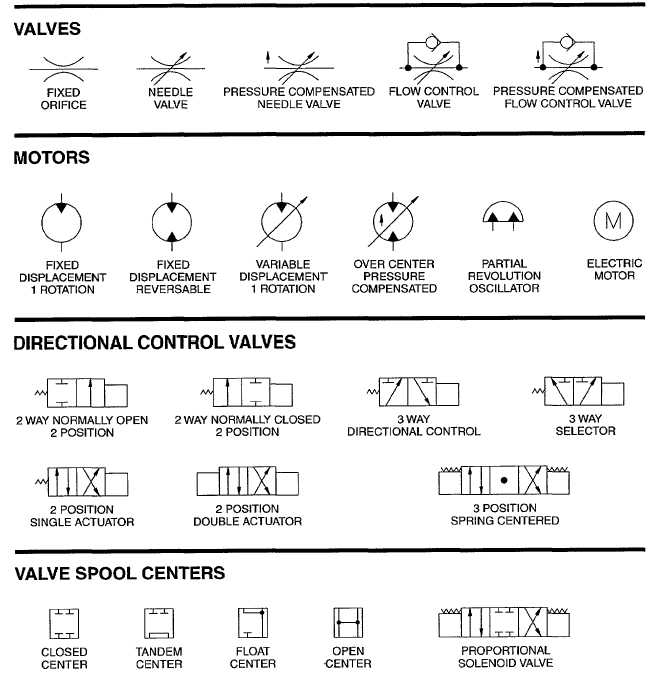
Figure C2. Hydraulic Schematic (Sheet 7 of 8)
1.1 General Fluid power systems are those that transmit and control power through use of a pressurized fluid (liquid or gas) within an enclosed circuit. Types of symbols commonly used in drawing circuit diagrams for fluid power systems are Pictorial, Cutaway, and Graphic.
Hydraulic Valve Symbols Autocad energyfabric
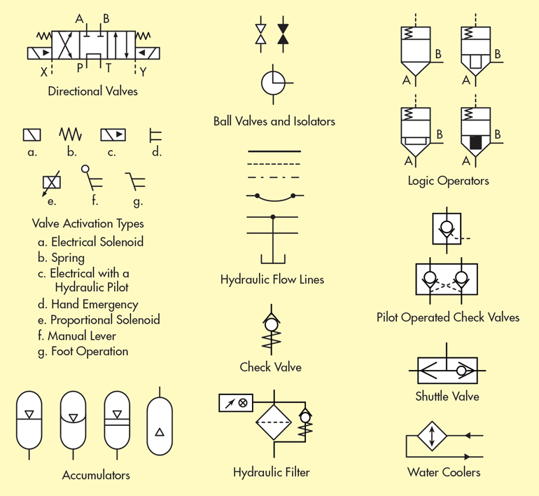
Reading fluids circuit diagrams - hydraulic & pneumatic symbols Reading fluids circuit diagrams - hydraulic & pneumatic symbols Dec 19, 2017 Below are some common illustrations of equipment located on fluids circuit diagrams, followed by descriptions of the most common elements.

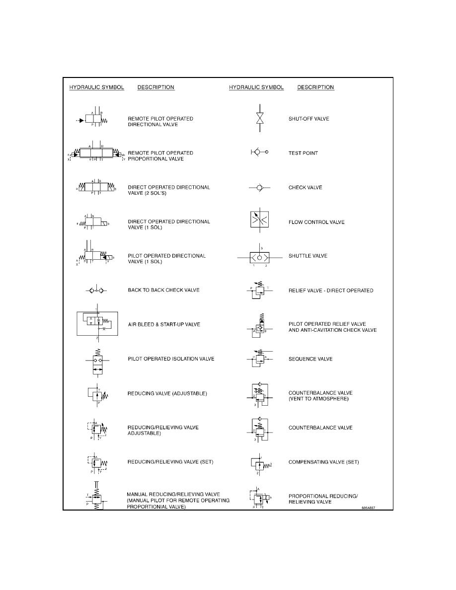
HYDRAULIC SYSTEM FOR BEGINNERS Mechanical Engineering Professionals
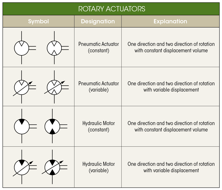
These are the circle, square and diamond. Ninety nine percent of hydraulic symbols use one of these three as a foundation. Pumps and motors of every kind are drawn using a circle, as are measuring instruments. Valves of every kind use the basic square as a start.
What’s the Difference Between Hydraulic Circuit Symbols? Machine Design
Hydraulic symbols provide a clear representation of each hydraulic component functions. Many hydraulic symbol designs are based industry standards such as DIN24300, ISO1219-1 or -2, ANSI Y32.10 or.

Hydraulic Flow Schematic Symbols
A hydraulic schematic diagram uses lines and symbols to provide a visual display of fluid paths within a hydraulic circuit. A hydraulic schematic also indicates the types and capabilities of components in the circuit. Basic hydraulic circuits use strategic placement of control valves and components to manipulate fluid and achieve specific results.
Hydraulic Symbols
In this lesson we'll review schematic symbols for common fluid power devices including fluid conductors, prime movers, pumps, reservoirs, actuators, directio.
Hydraulic symbols Lys for
For a hydraulic circuit, the symbols represent components (valves, pumps, motors) and systems. And both use industry standard symbols for components, which for hydraulic diagrams would include things such as valves, pumps, motors, and tanks. Hydraulic Reservoirs A hydraulic reservoir is used to hold the hydraulic fluid needed by the system.

Hydraulic pump circuit symbols Part 2 YouTube
The most commonly used hydraulic symbols are as follows: Hydraulic Reservoir A hydraulic reservoir stores hydraulic fluid. This is a must-have component in any hydraulic system. All hydraulic reservoirs are open to the atmosphere except in the case of those used in aircraft and submarines. Hydraulic Pump and Motor
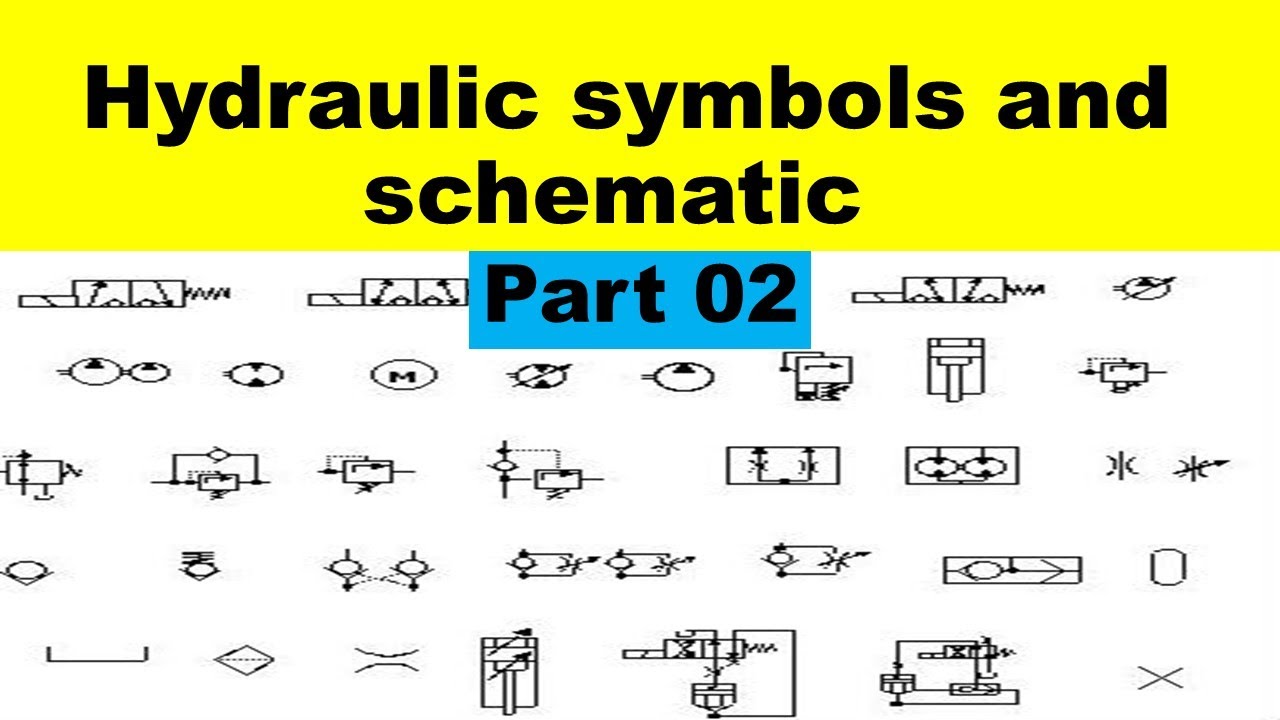
Hydraulic Symbols and Schematic For Beginners How to Read Hydraulic Drawing. Part 02
Hydraulic Schematic Symbols Accumulator Cylinder Double acting Directional Control Valve (manually operated) Dump Pumps Hydraulic System Components: Gear Pump Hydraulic Pump Symbol Hydraulic System Components : Accumulator Accumulator symbol Hydraulic System Components : Directional Control Valve
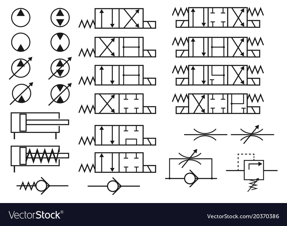
Set of hydraulic symbols Royalty Free Vector Image
H draulics ONLINE Basic Symbols PRESSURE OR RETURN LINE PILOT LINE TWO OR MORE FUNCTIONS IN ONE UNIT FLEXIBLE HOSE UNION CLOSED CONNECI'ION DIRECTION OF MOVEMENT DIRECTION OF ROTATION REGULATION POSSIBLE ELECTRIC SOLENOIDS WORKING IN OPPOSITE DIRECTIONS DIRECTION OF ROTATION LOOKING AT SHAFT PNEUMATIC HYDRAULIC TEST POM

A guide to common hydraulic symbols EngineeringClicks
Below we have summarised some of the most common symbols you may come across. Our technical sales engineers will be happy to help should you need any further help and assistance. Please get in touch on +44 (0)845-644-3640. Explore our Resource Library for more information: E-BOOK GUIDES HYDRAULIC CALCULATIONS ATEX SOLUTIONS A - Z GLOSSARY
What’s the Difference Between Hydraulic Circuit Symbols? Machine Design
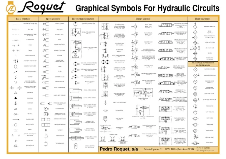
Basic symbols "Your One-Stop Hydraulics Resource" Call us now or— UK: 084Y644 3640 International: + 44 845 644 3640 Spool controls Graphical Energy transformation FIXED DISPLACEMENT PUMP SINGLE-ACTING HAND PUMP (e.g. 376) DOUBLE ACTING HAND PUMP (e.g. 27906) FIXED DISPLACEMENT REVERSIBLE MOTOR WITHOUT DRAIN FIXED DISPLACEMENT REVERSIBLE
Hydraulic Schematic Diagram Symbols Wiring Diagram
Hydraulics schematic symbols are a basic component of hydraulic circuit. Symbols for hydraulic systems are for functional interpretation and comprise one or more function symbols. Hydraulic symbols are neither dimensioned nor specified for any particular position. The following list is contains hydraulic schematic symbols to DIN ISO 1219.

What’s the Difference Between Hydraulic Circuit Symbols? Machine Design
Line styles in hydraulic schematics. In a hydraulic system schematic, the pipes, hose and tube assemblies are represented by lines. A number of different types of lines are used to represent different types of assemblies. As with all other hydraulic symbols, these symbols are issued and controlled by The International Standards Organization.
Hydraulic Schematic Diagram Symbols
What do circles, semi circles, squares, rectangles, diamonds and lines represent in hydraulic schematics? Circles and semi-circles are used to represent rotary devices such as pumps or motors. Triangular arrows represent the direction fluid takes in the pump or motor. • When circles represent pumps, the arrow faces outwards.
